Brazing Aluminum Alloy
Aluminium brazing using non-corrosive fluxes is the leading process for manufacturing automotive heat exchangers. Recently, this process has become more wide spread in the stationary Heating, Ventilation, Air-Conditioning and Refrigeration (HVAC&R) industry, both for domestic and commercial applications. The standard brazing process involves joining of components with a brazing alloy, typically an aluminium-silicon filler alloy. Al-Si brazing aluminum alloys have melting ranges from 577°C to 610°C, which is appreciably lower than the melting point range of the base Brazing aluminium alloy used for heat exchangers (630°C – 660°C). A consistent and on-going trend across all heat exchanger manufacturing sectors is towards lighter weight, accomplished by down-gauging of components. Also corrosion resistance is a key factor – particularly when there is no additional post brazing coating or treatment. These often contradictory trends call for brazing aluminium alloy having higher and higher post brazed strength. While alloys from the 7xxx (alloyed with Zn) and 2xxx (alloyed with Cu) series can be precipitation hardened to the highest strengths of any brazing aluminum alloys, their corrosion resistance without any additional coating is low and their solidus temperatures are below the melting range of currently used flux and filler metal combinations, and therefore they are not suitable for heat exchanger manufacturing by brazing.
The most common alloys used for aluminum brazing are from the 3xxx series (alloyed with Mn).
After being subjected to the high temperature during the brazing cycle, these alloys have relatively low post-braze mechanical strength. Higher strength is offered by alloys from the 5xxx series (alloyed with 2 to 5 wt% Mg) where post brazed strengthening is achieved by solid solution hardening or by the 6xxx series (alloyed with Mg and Si) which can be precipitation hardened.
As well as increasing post-braze mechanical strength, the addition of Mg to certain alloys allows for improved machinability. Machining is necessary for heat exchanger components such as connecting blocks and threaded fittings.There is however a certain limitation with the above mentioned alloys. They all contain magnesium. During the brazing cycle Mg negatively influences the process of oxide removal and it is generally accepted that Mg levels only up to 0.3% can be safely brazed with the standard brazing flux. This negative influence can be mitigated with the use of caesium containing compounds. The mechanism of Mg interference with the brazing process and the positive role of Cs additions to the flux in combating the effects of Mg are the subjects of the current paper.
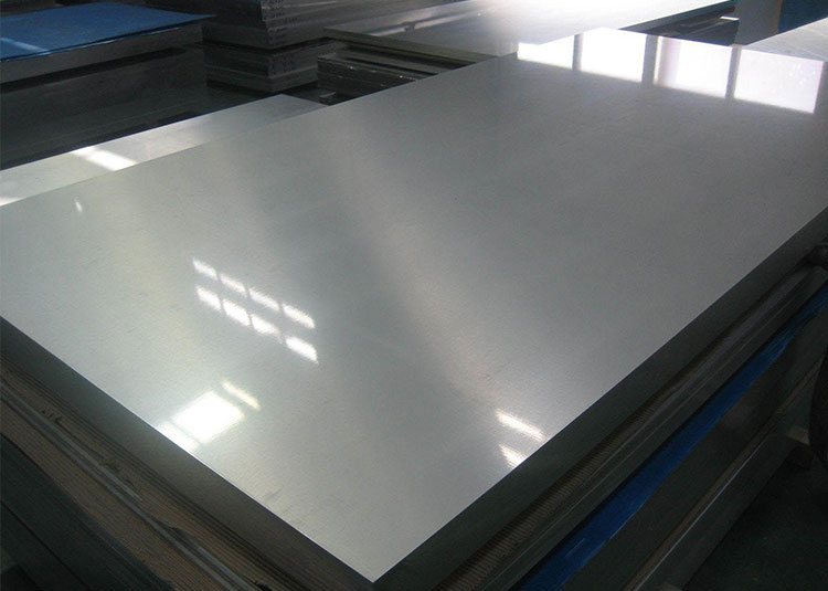
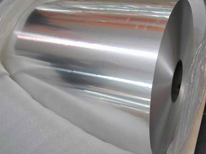
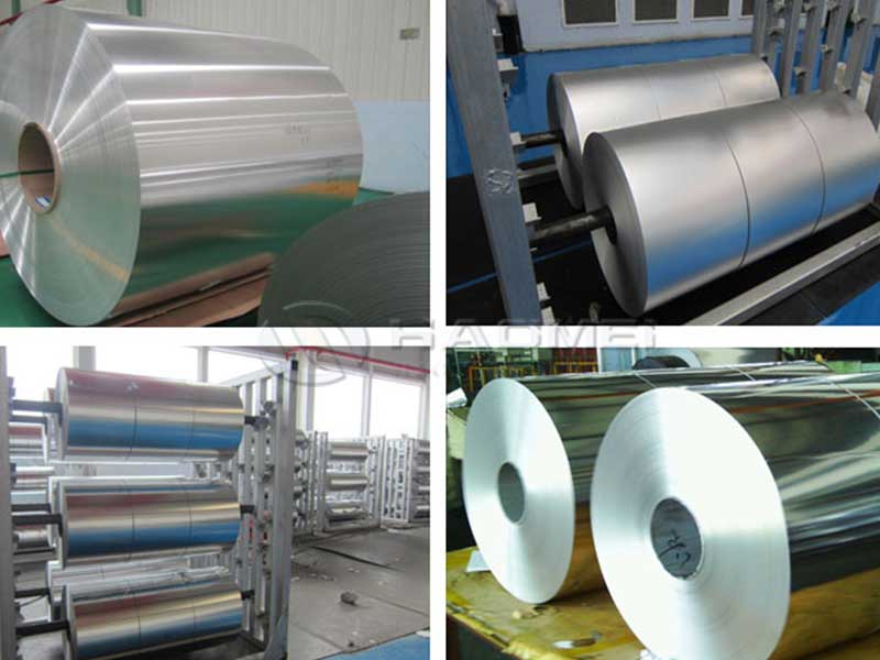
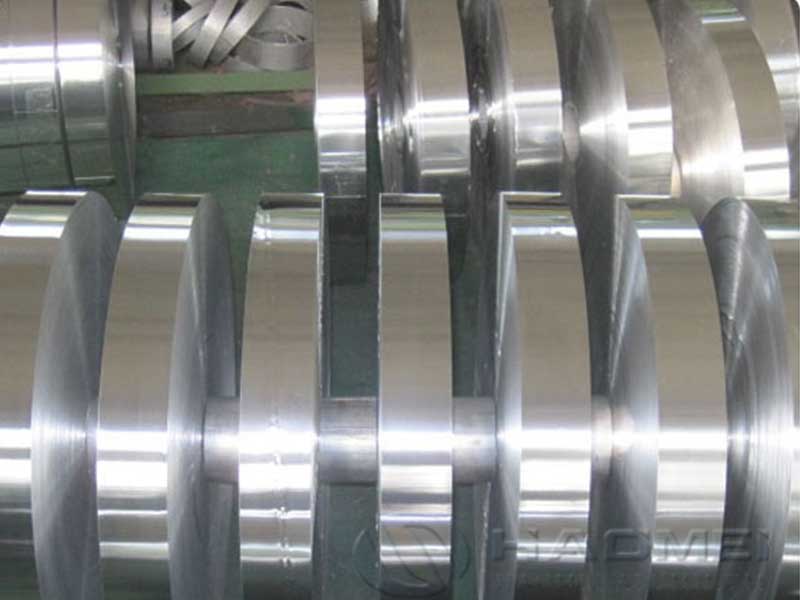
Specification and Data Sheet
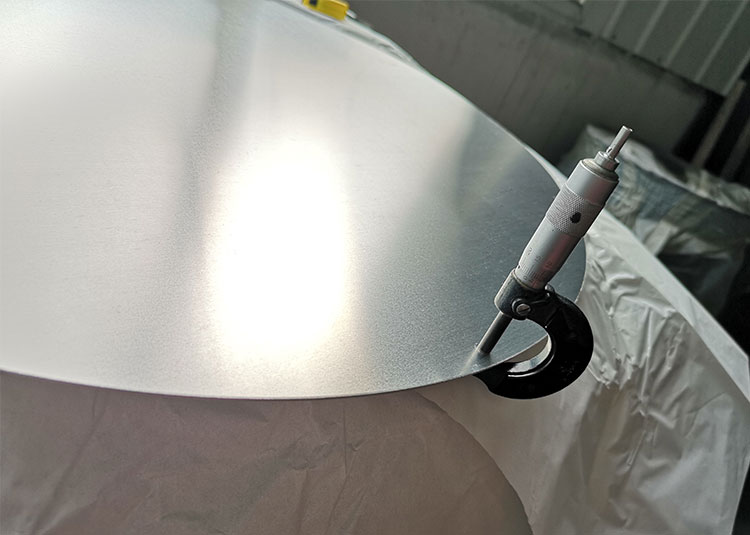
Surface
Specification and Data Sheet
| Brazing Aluminum Alloy Dimensions | ||
| Strips | Sheets | |
| Thickness | 0.051mm--3.0mm | 0.4mm--6.35mm |
| Width | 6mm--1600mm | 500--1600mm |
| Length | Max. 10000mm | |
| Edge quality | Trimmed 裁边 | Trimmed and slit; sawn |
|
Inside diameter 内径 |
305mm, 405mm, 505mm Paper core, Aluminium core, without core. | |
| Outside diameter 外径 | Max. 1600mm without connect point | |
| Cladding | |
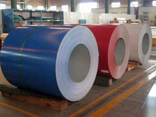
| Cladding | One side; Both sides |
| Cladding rate | 5%, 7.5%, 10%, 13%, 15% (other clad percentages available upon request) |
| Cladding tolerance |
Cladding thickness of 1.5%--<4%: +/-0.6 Cladding thickness of 4.0--6.0%: +/-1.0 Cladding thickness of 6.0--<=12.0%: +/-1.5 Cladding thickness of 12.0--20.0%: +/-2.0 |
Surface
| Surface | |
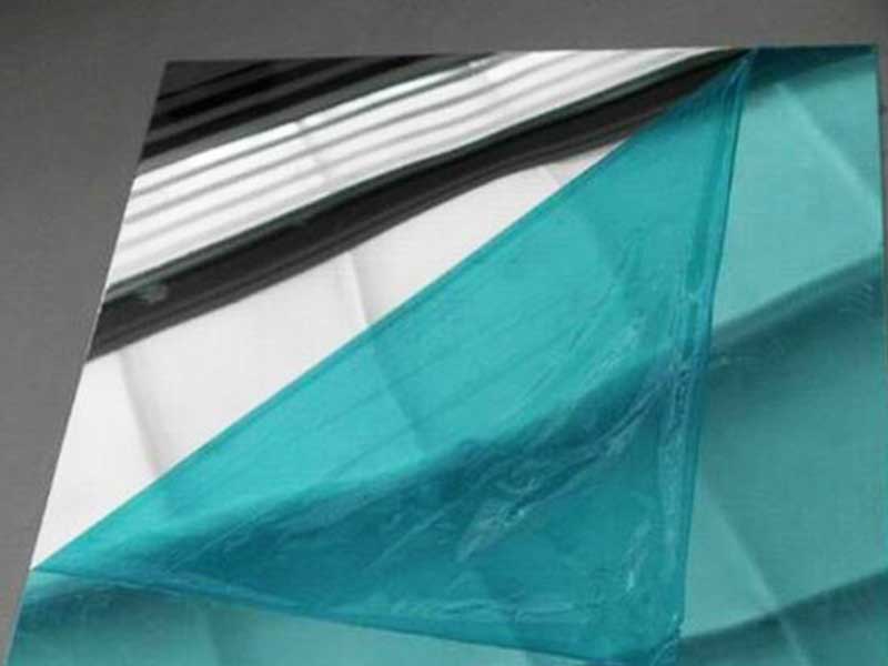
| Quality | Mill finish; for thickness 0.3--3.5mm, chemically degreased |
| Marking | Ink marking |
1> Tolerance according to EN and ASTM.
2> Higher thickness on request.
3> Special dimensions , tolerances, and alloys on request.
| Brazing Aluminum Alloy Dimensions Chemical composition | |||||||||||
| ALUMINIUM CLAD ALLOYS | Others | ||||||||||
| Alloy 合金 | Si | Fe | Cu | Mn | Mg | Cr | Zn | Ti | each | total | |
| Clad alloys for VCA-brazing according to EN573-3 | |||||||||||
| 4004 |
Min. max. |
9.0 10.5 |
- 0.8 |
- 0.25 |
- 0.10 |
1.0 2.0 |
- - |
- 0.20 |
- - |
- 0.05 |
- 0.15 |
| 4104(Containing0.02%-0.20% Bi) |
Min. max. |
9.0 10.5 |
- 0.8 |
- 0.25 |
- 0.10 |
1.0 2.0 |
- - |
- 0.20 |
- - |
- 0.05 |
- 0.15 |
| Clay alloys for CAB-brazing according to EN573-3 | |||||||||||
| 4343 |
Min. max. |
6.8 8.2 |
- 0.8 |
- 0.25 |
- 0.10 |
- - |
- - |
- 0.20 |
- - |
- 0.05 |
- 0.15 |
| 4045 |
Min. max. |
9.0 11.0 |
- 0.8 |
- 0.30 |
- 0.05 |
- 0.05 |
- - |
- 0.10 |
- 0.20 |
- 0.05 |
- 0.15 |
| 4047A |
Min. max. |
11.0 13.0 |
- 0.6 |
- 0.30 |
- 0.15 |
- 0.10 |
- - |
- 0.20 |
- 0.15 |
- 0.05 |
- 0.15 |
| Zn-containing clad alloys for CAB-brazing | |||||||||||
| 4343.ZN |
Min. max. |
6.8 8.2 |
- 0.8 |
- 0.25 |
- 0.10 |
- - |
- - |
0.8 1.2 |
- - |
- 0.05 |
- 0.15 |
| 4045.ZN |
Min. max. |
9.0 11.0 |
- 0.8 |
- 0.30 |
- 0.05 |
- 0.05 |
- - |
0.8 1.2 |
- 0.20 |
- 0.05 |
- 0.15 |
| Clad alloys for corrosion protection according to EN573-3 | |||||||||||
| 1050A |
Min. max. |
- 0.25 |
- 0.40 |
- 0.05 |
- 0.05 |
- 0.05 |
- - |
- 0.07 |
- 0.05 |
- 0.03 |
- - |
| 7072 |
Min. Max. |
- 0.7(Si+Fe) |
- 0.10 |
- 0.10 |
- 0.10 |
- - |
0.8 1.3 |
- - |
- 0.05 |
- 0.15 |
|
| All data in Wt.-%; Customer specific alloy composition on request. | |||||||||||
| 3××× alloys according to EN573-3 and ASTM 3××× | |||||||||||
| 3003 |
Min. max. |
- 0.6 |
- 0.7 |
0.05 0.25 |
1.0 1.5 |
- - |
- - |
- 0.10 |
- - |
- 0.05 |
- 0.15 |
| 3004 |
Min. max. |
- 0.30 |
- 0.70 |
- 0.25 |
1.0 1.5 |
0.8 1.3 |
- - |
= 0.25 |
- - |
- 0.05 |
- 0.15 |
| 3005 |
Min. max. |
- 0.6 |
- 0.70 |
- 0.30 |
1.0 1.5 |
0.20 0.6 |
- 0.10 |
- 0.25 |
- 0.10 |
- 0.05 |
- 0.15 |
| 3103Containingmax.0.10%(Zr+Ti) |
Min. Max. |
- 0.50 |
- 0.70 |
- 0.10 |
0.9 1.5 |
- 0.30 |
- 0.10 |
- 0.20 |
- - |
- 0.05 |
- 0.15 |
| 3105 |
Min. Max. |
- 0.6 |
- 0.7 |
- 0.30 |
0.30 0.80 |
0.20 0.80 |
- 0.20 |
- 0.40 |
- 0.10 |
- 0.05 |
- 0.15 |
| 5×××-non-heat-treatable alloys according to EN573-3 and ASTM 5××× | |||||||||||
| 5049 |
Min. max. |
- 0.40 |
- 0.50 |
- 0.10 |
0.50 1.10 |
1.60 2.50 |
- 0.30 |
- 0.20 |
- 0.10 |
- 0.05 |
- 0.15 |
| 5052 |
Min. max. |
- 0.25 |
- 0.40 |
- 0.10 |
- 0.10 |
2.2 2.8 |
0.15 0.35 |
- 0.10 |
- - |
- 0.05 |
- 0.15 |
| 5083 |
Min. max. |
- 0.40 |
- 0.40 |
- 0.10 |
0.40 1.0 |
4.0 4.9 |
0.05 0.25 |
- 0.25 |
- 0.15 |
- 0.05 |
- 0.15 |
| 6×××-non-heat-treatable alloys according to EN573-3 and ASTM 6××× | |||||||||||
| 6063 |
Min. max. |
0.20 0.60 |
- 0.35 |
- 0.10 |
- 0.10 |
0.45 0.90 |
- 0.10 |
- 0.10 |
- - |
- 0.05 |
- 0.15 |
| 6951 |
Min max. |
0.20 0.50 |
- 0.08 |
0.15 0.40 |
- 0.10 |
0.40 0.8 |
- - |
- 0.20 |
- - |
- 0.05 |
- 0.15 |
| 7×××-non-heat-treatable alloys according to EN573-3 and ASTM 7××× | |||||||||||
|
7020 Containing 0.08%-0.25% (Zr+Ti) and 0.08%--0.20% Zr |
Min. max. |
- 0.35 |
- 0.40 |
- 0.20 |
0.05 0.50 |
1.0 1.4 |
0.10 0.35 |
4.0 5.0 |
- - |
- 0.05 |
- 0.15 |
| Brazing Aluminum Alloy Physical Property Data of Strip Material | ||||||||||||||||
|
Alloy |
Temper |
Thickness (mm) |
Tolerance (mm) |
Clad Ratio (%) |
Tensile Strength (MPa) |
Yield Strength (MPa) |
Elongation (%) Min |
Application | ||||||||
| 3003 | H14 | 0.08~0.12 | ±0.005 | None | 150~200 | ≥120 | 1 |
Evaporator fin and plate |
||||||||
| 3003 | H26 | 0.3~0.35 | ±0.015 | None | 190~220 | ≥160 | 8 |
Glass mounting bracket material |
||||||||
| 3003 | H14 | 0.06~0.1 | ±0.005 | None | 150~200 | ≥120 | 1 |
Radiator fin and plate |
||||||||
|
4343/3003/ 4343 |
H14 | 0.06~0.1 | ±0.005 | 8~12 | 150~200 | ≥120 | 1 | |||||||||
|
4343/3003/ 4343 |
H14 | 0.08~0.12 | ±0.005 | 8~12 | 150~200 | ≥120 | 1 |
Parallel condenser fin |
||||||||
|
4343/3003/ 4343 |
H14 | 0.1~0.12 | ±0.005 | 8~12 | 150~120 | ≥120 | 1 |
Charge air cooler material |
||||||||
|
4045/3003/ 4045 |
H14 | 0.1~0.12 | ±0.005 | 8~12 |
150~200 |
|||||||||||
